
|
Illustrated Tour of the Installation Process |
|
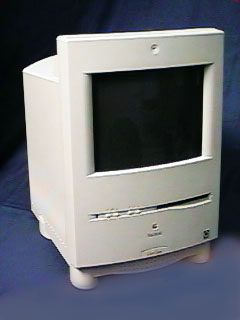
Steps to upgrade the Color Classic Resolution from 512x384 to 640x480 |
|
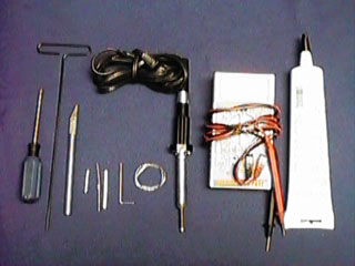
Tools You Need: |
|
|
Philips screw driver |
|
|
MacOpener™ |
Tool to open the Color Classic. It is a Torx-15, however you also can use an hex-tool # |
|
sharp knife |
used to cut the copper plane around "pin 8" (step 12, 14) |
|
a 1" solid wire (gauge 18) |
this piece is used to short out pins 8 and 10 (step 12) |
|
4.7 K½ resistor* |
only used for rev. "D" analog boards |
|
insulation tubing* |
only used for rev. "D" analog boards |
|
hex-tool # |
for the final adjustments to the screen |
|
solder |
|
|
solder iron |
|
|
Ohmmeter (any multi meter) |
optional to verify the connectivity |
|
Silicon |
used as adhesive |
|
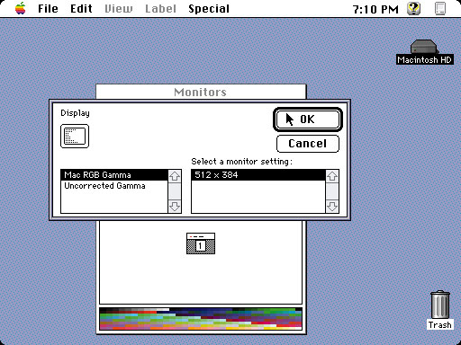
Step 1: |
Verify the proper operation of your Color Classic |
|
verify the current resolution in the "Monitor" Control Panel by clicking into the "option.." button |
|
Step 2: |
Prepare your computer |
|
Shut down your Mac properly. |

|
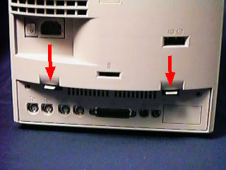
Step 3: |
Open your Mac |
|
Remove the two screws on each side of the back panel. |
|
Step 4: |
Remove the logic board |
|
Pull the logic board out of the chassis. |

|
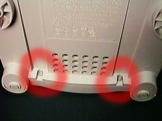
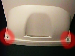
Step 5: |
Remove screws from back side |
|
Position the Color Classic with its screen down. |

|
Step 6: |
Remove the back chassis |
|
Lift and remove the back side of the chassis |

|
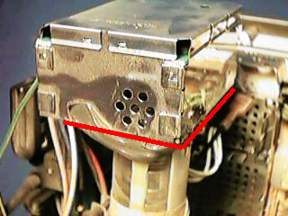
Step 7: |
Remove video board |
|
Locate the silicon which holds the video "box" on the
tube and along the metal edge with a sharp razor blade. |
|
Step 8: |
Disconnect cables |
|
Step 8a: |
Push on the tap to unlock while pulling on the first cable, located just beneath the power connector. |

|
Step 8: |
Disconnect cables |
|
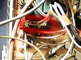
Step 8b: |
Pull on the X-Y-control cable, located on the left side. |
|
Step 8: |
Disconnect cables |
|
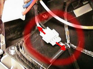
Step 8c: |
Pull on both ends of the microphone cable |
|
Step 8: |
Disconnect cables |
|
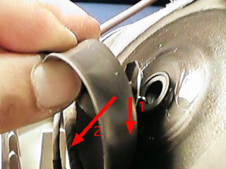
Step 8d: |
Make sure at lease 10 minutes have passed since power
off!!!! |

|
Step 8: |
Disconnect cables |
|
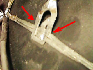
Step 8e: |
Disconnect the grounding cable, beware it has two hooks (arrows) over which the grounding line has to be moved. |
|
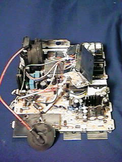
Step 9: |
Remove analog board |
|
Now pull the analog board upward until it clears the tabs, then remove it from the frame. |

|
Step 10: |
Remove metal shielding |
|
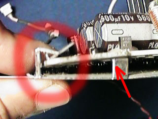
Squeeze the analog board and the metal shield so the tabs
are cleared (red circle) and slide the metal shield towards
the front. Watch for the one metal tap (arrow) it mostly get
caught in a hole preventing the slide. |
|
Step 11: |
Identify the revision and the location for the modification |
|
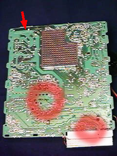
Identify the different revision of the analog boards by
there numbers. The board number is located on the top left
corner (arrow). |
|
Step 12: |
Modification on the "ZP1" area |
|
This change applies for both revisions of the analog
board. |


|
Step 13: |
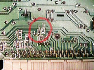
Modification on the "ID-select" area Rev "B" and "C" |
|
locate the location "J78" and "J79". |
|
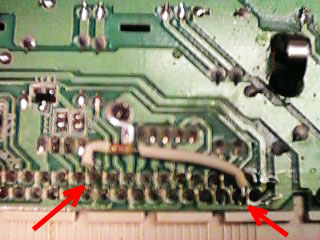
Step 14: |
Modification on the "ID-select" area Rev "D" |
|
Identify pin 20 on the edge connector. |

|
Step 15: |
Install the analog board back into the chassis |
|
Mount the metal shielding onto the analog board, install it into the chassis and connect the cables doing it in the reversed sequence as in steps: 10, 9 and 8. |
|
Step 16: |
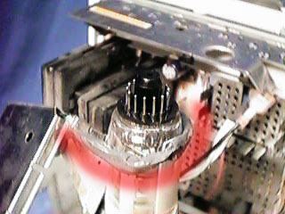
Install the video board |
|
apply some silicon onto the original silicon before
installing the video board back onto the tube. |
|
Step 17: |
Install the logic board |
|
install the logic board without closing the chassis. |

|
Step 18: |
Adjust the picture shape |
|
Step 18a: |
Using the Hex-tool, adjust the picture on the back side
as follows. |

|
Adjustment table |
|
|
SC |
for color adjustment, don't use |
|
GG |
for color adjustment, don't use |
|
BG |
for color adjustment, don't use |
|
RB |
for color adjustment, don't use |
|
GB |
for color adjustment, don't use |
|
BB |
for color adjustment, don't use |
|
VH: (vertical height) |
|
|
HW: (horizontal width) |
|
|
PB: |
|
|
KS: |
|
|
HS: (horizontal shift) |
|
|
VS: (vertical shift) |
|
|
PR |
|
|
Step 18: |
Adjust the picture focus & brightness |
|
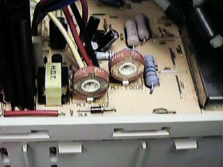
Step 18b: |
On the left side of the analog board there are two
potentiometers, the one toward the front is labeled "FOCUS",
the other one is for the brightness. |
|
Step 19: |
Close the chassis |
|
There is no need to remove the logic board in order to
close the back of the chassis. |
|
Step 20: |
Enjoy your increased resolution |
|
verify the new resolution in the "Monitor" Control Panel by clicking into the "option.." button |

|
Note: |
Disclaimer |
|
Individual results may vary. |
|
|
Copyright
©1998 MicroMac Technology
This page was last modified on July 10,
1998.